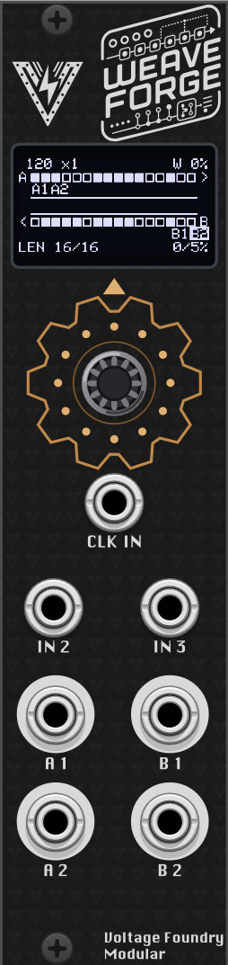
Hover the panel to zoom
WeaveForge — A Dual Shift-Register Sequencer
Overview
Dual shift-register sequencer for the ForgeSeries hardware, and a VCV Rack module built from the same code.
Two 16-bit shift registers clock in parallel. Each one is a Turing Machine in Tom Whitwell’s sense: a ring of bits that shifts on every clock, with one probability control deciding whether the bit coming round the loop flips on the way. At one end of that control the pattern is locked forever; at the other it never repeats; in between it is a loop that changes a note now and then.
What makes this module its own thing is WEAVE — one control deciding how much of each register’s incoming bit comes from the other register. At zero they are two independent sequencers. Turned up, motifs leak across and drift back. At full, the two registers chain tail-to-head into a single ring as long as both of them together, and the screen draws the braid while it happens.
Four outputs read windows out of those registers, and each one is assignable: notes, smooth modulation, gates or triggers, from either register or from the woven ring, at any depth and any rotation. So the same two registers can be two voices, one voice plus two correlated modulations, or a four-track drum machine.
Features
- Two 16-bit shift registers with independent length (2–16) and probability
- WEAVE — a continuous slide from two independent sequencers to one long one
- One-way coupling (
A▸B/B▸A) for a theme-and-answer pair - Four fully assignable outputs: source, type, window depth and rotation each
- Three one-click output layouts — two voices, voice + modulation, four drum tracks
- Quantized note outputs with 15 scales, root and transposition
- Gate and trigger outputs with a density control, not a fixed 50 %
- Internal clock or external, with multiplication and division either way
- Two assignable CV inputs; ten preset slots that store the patterns themselves
Check the module on ModularGrid.
User Manual
Front panel
| Jack | What it is |
|---|---|
| IN 1 | Clock. Always — this jack has no role menu. A rising edge advances the sequencer. |
| IN 2, IN 3 | Assignable modulation CV, 0–5 V. Destination and depth are set on the CV IN page. |
| A 1, A 2 | The left column of outputs, 0–5 V. |
| B 1, B 2 | The right column. |
The encoder turns to move through the menu, clicks to enter or leave a value, and — held for two seconds — returns to the module selector.
IN 1 is the clock and nothing else, unlike GravityForge and ChaosForge where that jack has a menu of jobs. Those modules run a simulation with a life of its own; a shift register has no life between clocks, so a WeaveForge with nothing patched to IN 1 would be a static voltage. An internal clock covers the unpatched case, and RESET and the pattern-lock gate are available as CV destinations on IN 2 / IN 3 instead.
What the output jacks carry is not fixed. The ROUTING page decides. In the default DUO layout each register owns a column — A1/A2 are register A’s note and gate, B1/B2 are register B’s — which is where the panel names come from. Any other layout is free to break that, and the screen always tells you the truth.
Everything is 0–5 V. Note outputs are 1 V/oct over five octaves.
The screen
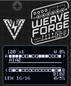
The home screen is the loom: both registers, the weave between them, and where every output is reading.
The two rows are the registers, and they run in opposite directions — register A left to right, register B right to left. That is not decoration. At WEAVE 100 % the chain becomes a visible racetrack: a bit leaves A’s right end, crosses down through the channel, travels back along B, and comes up into A’s left end. You can follow one round it with a finger.
Each cell is one bit:
| Drawn | Means |
|---|---|
| filled block | bit = 1, inside the active length |
| hollow block | bit = 0, inside the active length |
| shaded block | bit = 1, past the feedback point |
| small dot | bit = 0, past the feedback point |
So LENGTH is a boundary you can see, not a number to read: the point where the row goes dim. The dim cells are still moving, and an output rotated out there is still reading them — they show their bit value for exactly that reason — but they are not part of the loop. They are a running copy of what has passed through the feedback point, which is why they are drawn faint.
The newest bit is punched through for the first part of each step: whichever cell just arrived gets a hole in its middle at the entering end of the row. On a locked pattern that is the only thing on the row that changes, and it is how you tell a running module from a stopped one at a glance.
The small caret above each row points at the feedback tap — the last cell of the active length. That is the bit about to come round the loop, the one CHANCE decides whether to flip, and the one that leaves for the other register when the weave carries it across. Change LENGTH and the caret moves with the boundary where the row goes dim; they are the same fact seen two ways.
The channel between the rows is the weave. At 0 % the two rails are dashed with nothing crossing. As WEAVE comes up, strands appear crossing between them, more of them the higher it goes, until at 100 % it is a full braid — and the whole braid travels, so you can see the cloth being drawn through. It moves one cell along per clock, the same rate the bits do, whatever WEAVE is set to. The strands follow DIR, so a one-way weave shows them going one way only.
A dot crossing the channel is a bit that actually jumped. WEAVE is a probability, so the braid says how much crossing is likely and the dot says what happened: it leaves the sending register’s feedback cell and arrives at the receiving register’s entering end, where the next step draws it as the new bit. At a low WEAVE you get an open, quiet channel with something through it now and then; at 100 % there is one every clock, each way.
The labels under each row are the output jacks, sitting at the cell they
read. A1 and A2 under register A’s row mean those two jacks are reading it.
A label inverts to a solid block while its jack’s gate or trigger is high, so you
can see which outputs are speaking as well as where they read from. Note and
modulation outputs have a value at all times, so they never light — their label
is a map, not a blinker. Set a jack’s ROTATE and watch its label walk along the
row.
The bar between a row and its labels is where that output reads from. A jack does not read one cell — it reads DEPTH of them, and the bar covers exactly those, starting at its ROTATE. That is the group of bits being turned into the note, the modulation, or the gate decision at that jack. Turn DEPTH and the bar grows; turn ROTATE and it walks along the row. When several jacks read the same cells the bars overlap into one, and while you are editing a jack its own bar is drawn solid so you can pick it out.
A dotted line joins each label to the cells it reads. Two jacks reading the same place cannot both have their label printed there, so the second one sits along to the side — follow the dots rather than reading straight up from the label, and you will always land on the right cells.
Header: the tempo large on the left, then the clock rate — prefixed EXT
when an external clock is running and the number is the measured tempo rather
than the one you set; weave amount on the right.
Status line: the two lengths, and the two probabilities.
Turning LENGTH, CHANCE, WEAVE, DIR, BPM, RATE, DEPTH or ROTATE hands the screen back to the loom while you adjust, with the value in a strip along the bottom — so the number and its effect are visible at the same time. It returns to the page a few seconds after you stop.
Menu map
Click the encoder to enter a value, turn to change it, click again to leave.
| Page | Rows |
|---|---|
| home | the loom |
| REG A | LENGTH · CHANCE · RANDOMIZE · INVERT · CLEAR · FILL |
| REG B | as A |
| WEAVE | AMOUNT · DIR |
| CLOCK | BPM · IN PPQN · RATE |
| SCALE | ROOT · SCALE · TRANSPOSE |
| ROUTING | ROUTING |
| OUT A1 / A2 / B1 / B2 | SOURCE · TYPE · DEPTH · ROTATE · + two more |
| CV IN | IN2 DEST · IN2 DEPTH · IN3 DEST · IN3 DEPTH |
| SETTINGS | TIMEOUT · BOOT MENU |
| PRESETS | SLOT · SAVE · LOAD · RANDOM |
REG A / REG B
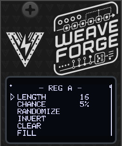
The two registers are identical and independent. Everything here applies to both.
LENGTH (2–16) — how many bits are in the loop. The bit at position LENGTH−1 is the one fed back round to the start, so LENGTH is the number of steps before the pattern comes round again.
CHANCE (0–100 %) — the probability that the bit coming round the loop flips on the way. This one control is the whole character of the module, and both ends of it are settings, not extremes to avoid:
| CHANCE | What you get |
|---|---|
| 0 % | Locked. The pattern repeats every LENGTH steps, forever. |
| 10–30 % | A loop that changes a note now and then. |
| ~50 % | Maximum drift — a new sequence every time round. |
| 100 % | Locked, inverting. A pattern twice LENGTH long. |
That last row is worth knowing: always-flip is exactly as deterministic as never-flip. At LENGTH 16 and CHANCE 100 you get a locked 32-step phrase.
RANDOMIZE rolls new bits for this register. INVERT flips all sixteen — the same rhythm inside out. CLEAR and FILL set them all to 0 or 1, which are the two starting points to hand-build from once the bit editor lands.
Shortening LENGTH is destructive. The region above the feedback point is overwritten within a few clocks, so turning LENGTH back up does not bring the longer pattern back. If you like a pattern, save it to a slot — the register contents are stored in the preset, which is the only way to keep one.
WEAVE
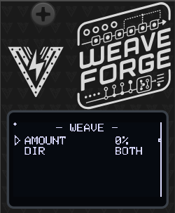
The module’s signature control, and the one the screen draws literally.
AMOUNT (0–100 %) — the probability, evaluated fresh for each register on every clock, that its incoming bit is taken from the other register’s outgoing bit instead of its own. CHANCE still applies afterwards, to whichever bit was chosen.
| AMOUNT | Behaviour |
|---|---|
| 0 % | Two unrelated Turing Machines that happen to share a clock. |
| ~50 % | Motifs leak across and drift back — related, never identical. |
| 100 % | The tails swap every clock: one ring, as long as both together. |
At 100 % with both lengths at 16 that is a locked 32-step phrase spread across two outputs — something no amount of turning a single Turing Machine’s knob will give you. The two lengths do not have to match: 5 and 3 chain into a ring of 8.
DIR — BOTH, A▸B or B▸A. One-way is the most useful of the three in
practice: with A▸B, register B becomes a variation on A that cannot
contaminate it. A stays the theme; B is the answer.
CLOCK
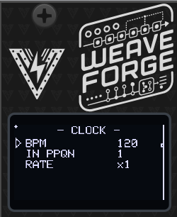
BPM (20–300) — the internal tempo, used whenever no external clock is
running. When one is running, this row shows the derived tempo with an E
after it, and the number you set is remembered for when the cable comes out.
IN PPQN (1, 2, 4, 8, 24) — how many pulses the clock arriving at IN 1 sends per beat. This is a description of your clock source, not a setting that changes the sequencer: 4 means you are feeding it sixteenth notes. It does nothing when the internal clock is running.
RATE — steps per beat, and it means the same thing whether the tempo comes from IN 1 or from BPM:
| RATE | One step every… |
|---|---|
/16 /8 /6 /4 /3 /2 | 16, 8, 6, 4, 3 or 2 beats |
x1 | beat — the tempo as set |
x2 x3 x4 x6 x8 x16 | 1/2, 1/3, 1/4 … of a beat |
x1 is the tempo on the header, so the module boots stepping at exactly the
number it displays. The table is symmetric, so a click one way is the mirror of
a click the other. Multiplied steps are locked to the incoming clock’s beat
rather than free-running, so they stay in time as the tempo moves.
The sequencer keeps playing on its internal tempo if the external clock stops or is unpatched.
SCALE
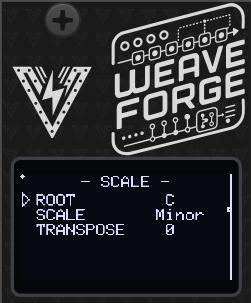
Applies to every NOTE output; there is one scale for the whole module, which is what makes two note outputs sound like one instrument rather than two.
ROOT (C–B) and SCALE — chromatic, major, minor, the modes, both pentatonics, harmonic and melodic minor, whole tone, diminished and blues. Together they build the set of notes the outputs can land on.
TRANSPOSE (−24 to +24 semitones) — shifts every note output.
ROUTING
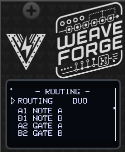
One row, and it is the fastest way to change what the module is. Picking a layout configures all four jacks at once, and the four lines below the row show what it did.
| ROUTING | A1 | B1 | A2 | B2 | The module is… |
|---|---|---|---|---|---|
DUO | NOTE A | NOTE B | GATE A | GATE B | two voices |
MONO | NOTE A | GATE A | MOD A | MOD B | one voice plus two modulations |
PULSE | TRIG A | TRIG A (rot 8) | TRIG B | TRIG B (rot 8) | a four-track drum machine |
Picking a layout stamps the jacks and then steps out of the way. Every field
on every OUT page stays editable afterwards, and once you change one this row
reads CUSTOM. Bring the jacks back into line with a layout and it names that
layout again — nothing is remembering that you edited anything.
Each layout keeps WEAVE meaningful: in DUO it merges two voices into one long shared phrase, in MONO it slides the second modulation from unrelated to locked with the melody, and in PULSE it merges two independent drum patterns into one.
OUT A1 / A2 / B1 / B2
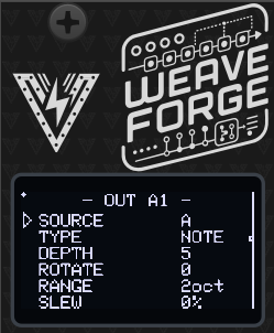
One page per jack, six rows each. The last two change meaning with TYPE.
The pages come in panel order — down the left column, then down the right — so turning the encoder past A1 lands on A2 below it rather than jumping across to B1. The ROUTING page’s summary and the Rack context menu list them the same way.
SOURCE — A, B, or AB. AB is the two registers as one 32-position
ring, which is what WEAVE at 100 % actually makes them.
TYPE
| TYPE | Emits |
|---|---|
NOTE | A quantized pitch, 1 V/oct. |
MOD | A stepped voltage — the original Turing Machine’s main CV output. |
GATE | High while the jack fires, low at the first step where it does not. |
TRIG | A fixed-width pulse each time the jack fires. |
DEPTH (1–8 bits) — how many bits this jack reads. More bits, finer resolution.
ROTATE — where in the register it reads. This is the highest-value control
on the page: four jacks tapping the same register at different offsets are
four phase-shifted copies of one pattern. Set a gate four steps behind its note
and you have a canon; do it across a drum kit and you have four tracks that
cannot drift apart. Its range follows SOURCE — 0–15 for a single register, 0–31
for AB.
Fifth row, per TYPE:
NOTE▸ RANGE (1–5 octaves) — the span the pattern is spread across. DEPTH sets resolution and RANGE sets span, so the two stay independent: 3 bits over 2 octaves is a sparse, singable line; 7 bits over the same 2 octaves wanders finely through it.MOD▸ LEVEL (0–100 %) — output scaling.GATE/TRIG▸ THRESH (0–100 %) — how often it fires. The bits are compared against this threshold rather than a single bit being read, so a gate output has a density control: 12 % is a sparse kick, 88 % a busy hat — and both are still locked to the same register as the melody. At DEPTH 1 and THRESH 50 % it is exactly the classic behaviour.
Sixth row, per TYPE:
NOTE/MOD▸ SLEW (0–100 %) — glide between values.TRIG▸ WIDTH — pulse length in milliseconds.GATEhas no sixth parameter and shows-.
CV IN
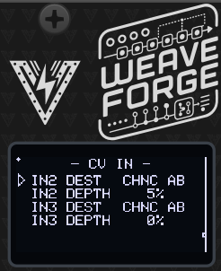
IN2 DEST / IN3 DEST — what that input modulates:
| Destination | Notes |
|---|---|
OFF | nothing |
LEN A LEN B LEN AB | pattern length |
CHNC A CHNC B CHNC AB | probability |
WEAVE | the coupling |
TRANS | transposition of every note output |
ROTATE | every jack’s rotation together — moves all the taps |
RESET | gate: restarts both patterns from a known state |
LOCK | gate: holds the patterns while high |
IN2 DEPTH / IN3 DEPTH (0–100 %) — how much. Length, probability and weave are trims around whatever the menu is set to, so a centred CV leaves the panel setting alone.
RESET and LOCK act on the level of the input and ignore depth. LOCK forces
probability to zero while it is high, which is the quickest way to freeze a
phrase from outside the module, and it wins over a CHANCE knob at 100 %.
SETTINGS
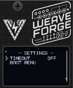
TIMEOUT — how long the menu waits before dropping back to the loom: OFF,
2, 5, 10 or 20 seconds.
BOOT MENU — returns to the module selector, the same as holding the encoder for two seconds. The selector is also the only way into the calibration wizard.
PRESETS
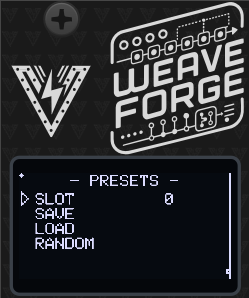
Ten slots. Slot 0 is loaded automatically at power-on, so save the patch you want to start with there.
SLOT picks the slot; SAVE and LOAD do what they say. A dot in the top-left corner of the screen means the live state differs from what is stored.
RANDOM rolls a new patch: new bits in both registers, new lengths and probabilities, a new weave. It deliberately leaves the output routing, the CV destinations, the scale and the clock alone — those are decisions you made on purpose, and rerolling them would turn “give me a new phrase” into “break my patch”. It does not write a slot, so a saved patch is one LOAD away.
The register contents are part of a preset, not just the settings. That is the point: a preset that restored the right length and the wrong bits would have restored nothing you cared about.
Patch ideas
- Two voices, converging. DUO, both lengths at 16, CHANCE around 25 %. Take A1/A2 to one voice and B1/B2 to another, then bring WEAVE up slowly from zero. Two unrelated lines pull together into one long phrase spread across both voices. This is the module in one knob.
- Theme and answer. DIR
A▸B, WEAVE around 60 %. B follows A and can never disturb it. - A drum machine off the bass line. PULSE, then set THRESH per track — low for the kick, high for the hats. The rhythm and the melody come from the same register, so they are locked together by construction.
- Canon. DUO, then set A2’s ROTATE to 4. The gate plays the pattern four steps behind the note.
- Keep one. Let it drift until something good goes past, pull CHANCE to 0 to
freeze it, and save the slot. Or patch
LOCKand freeze it with a footswitch. - A very long loop. Both lengths 16, WEAVE 100 %, CHANCE 0. One locked 32-step phrase. Set CHANCE to 100 instead for a 64-step one.
In VCV Rack
The Rack module runs the same firmware against a hardware shim, with the OLED emulated pixel for pixel, so it behaves identically to the panel.
Drag the encoder to scroll and click to select. With the mouse over the module,
[ and ] turn the encoder one detent and space clicks it.
Everything on the panel is also on the right-click menu — Weave, both registers with their pattern actions, the output matrix, clock, scale and CV routing — with real sliders and option lists instead of relayed encoder turns. The context menu also carries an input CV range setting (0–5 V like the hardware, ±5 V or 0–10 V) and an encoder sensitivity setting.
Saving a Rack patch stores the live state, including the patterns themselves, so a reloaded patch plays the phrase you left it on.
Hardware Calibration
The module ships with sensible default values, but for best precision — especially when using the quantized note outputs — you should run the hardware calibration wizard once after building or assembling the module.
Calibration covers two things:
Output trim: the output op-amp gain is set with on-board trimmers so every output jack delivers exactly 5.00 V at full scale. This is purely a hardware adjustment — there is no software output scaling.
CV input calibration: each CV input is measured at two known reference voltages (1 V and 3 V) to build a per-channel linear correction (mv = scale × reading + offset) that compensates for resistor tolerances and ADC offset. This is done with external references and is independent of the module’s own outputs, so any output-trim error does not propagate into the input calibration.
Calibration data is stored in a dedicated area of non-volatile memory separate from presets, so it survives firmware updates and preset load/save operations.
What you need
- A multimeter capable of measuring DC voltage to at least two decimal places (for the output trim).
- A stable, known 1 V and 3 V source for the CV inputs — for example a precision voltage reference, a bench power supply, or a calibrated sequencer/quantizer output — and a patch cable to connect it.
Running calibration
The wizard has 5 steps: one output trim followed by four CV input captures (1 V and 3 V on each of the two inputs).
Power on the module from your Eurorack supply while holding the encoder button pressed, which opens the module selector. Release the button, scroll to CALIBRATE at the bottom of the list and click. (From a running module you can get to the same screen with SETTINGS → BOOT MENU, or by holding the encoder for two seconds.) Click the encoder at the welcome screen to start.
Calibration belongs to the board, not to any one module: one run covers every module in the firmware, and the wizard reboots back to the selector when it is done.
⚠️ Calibrate on Eurorack power, not the MCU’s USB port — USB cannot drive the outputs to full scale, so the trim would be wrong. Never connect Eurorack power and USB at the same time, as this could damage the module.
Step 1 — Output trim (
1/5 OUTPUT TRIM): All four outputs are driven to full scale. Using a multimeter set to DC voltage, probe each output jack in turn and adjust its corresponding trimmer potentiometer on the PCB until the reading is exactly 5.00 V. When all four outputs read 5.00 V, press the encoder to continue.Steps 2–5 — CV input capture (
2/5…5/5): The display asks for a specific reference voltage on a specific input, in turn:2/5 CV1 INPUT 1V— apply 1 V to CV input 13/5 CV1 INPUT 3V— apply 3 V to CV input 14/5 CV2 INPUT 1V— apply 1 V to CV input 25/5 CV2 INPUT 3V— apply 3 V to CV input 2
For each step, apply the requested voltage to the named input. The screen shows a live voltage reading so you can confirm the signal is stable; when it is steady, press the encoder to capture (256 ADC samples are averaged). Repeat for all four steps.
Review and save: The display shows the derived per-channel scale and offset for a sanity check. Press the encoder to save and reboot. The module restarts with calibration applied.
Tip: Calibration only needs to be run once. Re-run it if you replace any resistors or trimmers on the board, or if CV tracking feels off after assembly.
Firmware Update
- Download the latest firmware from the Releases section of the GitHub repository.
- Connect the module to your computer using a USB-C cable while holding the small BOOT (B) button. The CPU can be removed from the module as it’s socketed to the main board if desired. Firmware loading can be done with the CPU removed.
- A new drive will show on your computer named RPI-RP2. Copy the
.uf2file to the module USB drive. After copy is finished, the module will reboot and the new firmware will be loaded.
Troubleshooting
- No Power: Ensure the module is properly connected to the power supply and the power jumper is set correctly.
- Nothing happens: This module does not run without a clock. Patch one to IN 1, or check that the CLOCK page’s BPM is set — the internal clock takes over whenever no external one is arriving.
- The pattern never changes: CHANCE is at 0 on both registers, or a
LOCKgate is high on one of the CV inputs. Both are deliberate freezes. - The pattern will not settle: CHANCE near 50 % is maximum drift. Come down to 10–30 % for a loop that changes occasionally, or to 0 to lock it.
- A gate output fires constantly or never: check that jack’s THRESH — it is a density control, and 0 % and 100 % are silence and a solid gate.
- Note outputs are all the same pitch: check RANGE on that jack, and that the scale has more than one note enabled.
Powering
The module uses only 5V internally. This can be provided directly by a Eurorack supply with a 5V rail, or taken from the 12V line and converted to 5V on-board. The source is selected with an on-board jumper: closing the center pin to INT REG takes power from the Eurorack 12V supply, while closing the center pin to EURO takes power from the 5V rail (requires a 16-pin cable). It can also be powered from the USB-C jack on the microcontroller board.
Never connect both the Eurorack power and the USB-C power at the same time. The module might be damaged or even damage your computer if both are connected. The module is designed to be powered from either source, not both.
Specifications
- Power Supply: 12V or 5V jumper selectable
- Input CV Range: 0–5V
- Output CV Range: 0–5V
- Dimensions: 6HP
- Depth: 40mm
- Current Draw: 60mA @ +12V or +5V
Contact
For support and inquiries, please open an issue on the GitHub repository.
Acknowledgements
The shift register is Tom Whitwell’s Turing Machine, by way of Hemisphere Suite’s ShiftReg. The assignable output matrix is the good idea from Phazerville’s Enigma. Thanks for the inspiration!
License
Source code is GPL-3.0-or-later — see the LICENSE in the source repository.
Panel designs, graphics, module names and the Voltage Foundry Modular brand are copyright and are not covered by that licence; see LICENSE-ASSETS.md.