Hover the panel to zoom
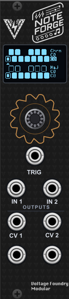
Note Forge
Forge SeriesDual CV quantizer with per-channel scales, envelopes and glide.
NoteForge - A Dual Quantizer Eurorack Module

Introduction
NoteForge quantizes analog control voltages into musical notes. It has two fully independent quantizers: each takes a pitch CV, snaps it to a scale you can edit note by note, and emits a quantized CV plus a gate or envelope.
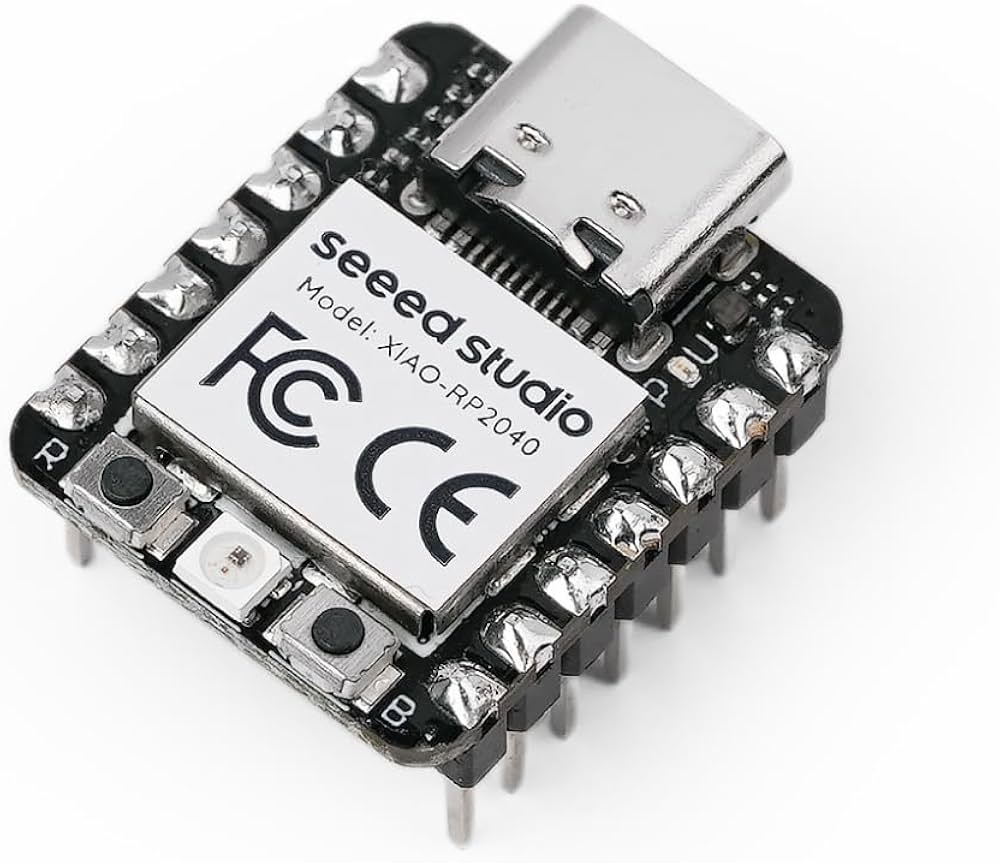
Part of the Forge series of modules, which share a single hardware platform based on the Seeed XIAO RP2040. The hardware schematics and design files are open-source and available in the hardware repository.
NoteForge also runs as a VCV Rack plugin — not a reimplementation, but the actual firmware running inside Rack with the OLED emulated pixel for pixel. See docs/VCVRack_Plugin.md.
Features
- Two independent quantizers, each with its own 12-note scale mask
- 15 built-in scales in any root, plus free per-note editing on the keyboard screen
- 12-bit quantized CV output on both channels (0–5 V, 1V/oct, 5 octaves)
- Boundary hysteresis so a CV resting on a note edge never chatters
- Per-channel gate/envelope output: AD envelope, fixed trigger, or gate
- Sync on trigger input, on note change, or both
- Per-channel octave shift, glide (portamento) and a note settle window
- Settle suppresses the notes an input sweeps through between two pitches
- Per-channel sample & hold: latch the note on a trigger and ignore the input between them
- IN 2 can become a transposition CV, stepping both channels in scale degrees
- 10 preset slots, with slot 0 loaded automatically at power-on
- Two-point CV input and output calibration wizard
- OLED display and rotary encoder for everything
Interface
| Jack | Direction | Meaning |
|---|---|---|
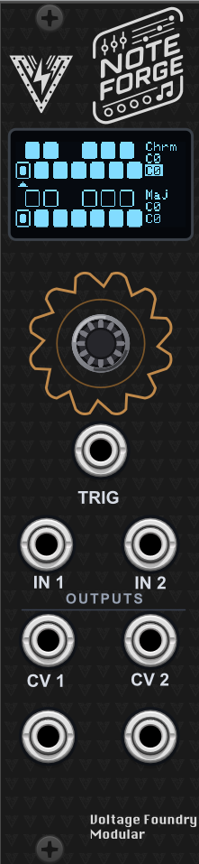
| TRIG | in | Trigger input (0–5 V) |
| IN 1 | in | Pitch CV for channel 1 (0–5 V) |
| IN 2 | in | Pitch CV for channel 2, or transposition CV (0–5 V) |
| OUT 1 | out | Quantized CV, channel 1 (12-bit, 0–5 V) |
| OUT 2 | out | Quantized CV, channel 2 (12-bit, 0–5 V) |
| GATE 1 | out | Gate / envelope, channel 1 (0–5 V) |
| GATE 2 | out | Gate / envelope, channel 2 (0–5 V) |
Getting Started
- Connect the module to a suitable power source and power it on.
- The display shows a splash screen, then the module name and version.
- Settings load from preset slot 0. On a fresh module that means channel 1 chromatic and channel 2 in C major.
- Patch a pitch CV into IN 1 and take the quantized result from OUT 1.
Using the Module
The keyboard screen (home)
The home screen shows one piano keyboard per channel:
- Filled key — the note is in the channel’s scale.
- Outlined key — the note is excluded; incoming CV never lands on it.
- Dotted key — the note the channel is playing right now.
The column on the right of each keyboard shows the selected scale, the root and octave offset, and the live note. The live note is drawn inverted while that channel’s gate/envelope is running.
Turning the encoder walks across the 12 keys of channel 1, then the 12 keys of channel 2 — the arrow between the keyboards points up at a channel 1 key and down at a channel 2 key. Click to toggle the note under the cursor. Keep turning past the last key to reach the menu pages.
Menu pages
Turning the encoder past the keyboards steps through:
| Page | Contents |
|---|---|
| SCALES | Scale and root per channel |
| CH1 PITCH | Mode, octave, settle and glide for channel 1 |
| CH2 PITCH | The same for channel 2 |
| CH1 GATE | Mode, attack, decay, sync and level for channel 1 |
| CH2 GATE | The same for channel 2 |
| ROUTING | IN 2 role, transpose range, and per-channel transpose enables |
| SETTINGS | Screen timeout, preset slot, save, load, load defaults |
A hollow arrow means the row is selected; click to start editing and the arrow fills in. Turn to change the value, click again to confirm. Spinning the encoder quickly accelerates the change. A dot in the top-left corner means there are unsaved changes.
The screen returns to the keyboard after the configured timeout (default 5 s, disable it on the SETTINGS page).
Choosing a scale
Changing SCALE or ROOT on the SCALES page writes straight into that channel’s note mask — there is nothing to confirm. Scrolling through the scales with a CV patched is therefore audible: you hear each one as you land on it, and the keyboard screen redraws to match.
The note mask stays the source of truth for what the quantizer plays, so you are free to toggle individual keys on the keyboard screen afterwards and build something that is not a named scale at all. The trade-off is that touching SCALE or ROOT again rebuilds the mask and replaces those manual edits — so hand-edit after picking the scale, not before.
If you switch every note off, the channel falls back to chromatic rather than freezing — the sounding note is marked with a small dot so it is obvious what happened.
Gate and envelope
Each channel drives its GATE jack in one of three modes:
- ENV — attack/decay envelope, retriggerable. Attack 0–2000 ms, decay 0–4000 ms.
- TRIG — a fixed 10 ms pulse at full level, for clocking other modules.
- GATE — follows the TRIG input level directly.
SYNC decides what fires it:
- TRIG — a rising edge at the TRIG input.
- NOTE — the quantized note changed.
- BOTH — either.
LEVEL scales the output from 0–100 %.
Pitch controls
- MODE —
TRACKorS&H. See below. - OCT — shifts the output ±3 octaves, applied after quantization, so the result always stays in the scale.
- GLIDE — portamento between notes, 0–100 % (up to a 500 ms time constant).
- SETTLE — 0–50 ms. How long a new note has to hold before the output plays it. See below.
Why SETTLE exists
When the input jumps between two distant notes it does not arrive at the ADC as a clean step: the input smoothing takes a few loop iterations to converge, and a quantizer that simply follows its input plays every note it crosses on the way. That is heard as a short sweep up to the target note rather than a clean jump.
SETTLE requires a new note to hold for a given time before the output follows. The transient notes are each held for well under a millisecond, so none of them survives the window and the output steps straight from the old note to the new one. An input that genuinely is moving slowly still plays every note it passes through, because each one holds for longer than the window — so this is a de-glitcher, not a slew limiter.
The default is 5 ms. Set it to 0 for the old immediate-follow behaviour, or raise it if your source is noisy or slewed.
This replaces the SENS (sensitivity) control from earlier firmware. SENS was a gain trim on the incoming pitch CV, which is the wrong tool once the calibration wizard has fitted the input scale properly — any setting other than unity detunes the module and makes it quantize to the wrong note.
Sample & hold
Each channel’s pitch MODE decides when the output is allowed to move:
- TRACK — follow the input continuously, subject to the settle window.
- S&H — latch the quantized note on a rising edge at TRIG and hold it until the next one.
In S&H nothing the input does between triggers reaches the jack: no sweeps, no
drift from a slewed source, no chatter from a noisy one. It is the unconditional
version of what SETTLE does statistically, and it is what you want when the
pitch comes from something that moves continuously — an LFO, a slew limiter, a
hand on a joystick.
SETTLE keeps working in this mode, as the sample delay. A sequencer puts out its pitch and its gate at the same instant, so at the moment of the trigger the pitch CV may still be in transit; SETTLE is how long the module waits after the edge before believing what it reads. The default 5 ms is a good starting point.
The first reading after power-on is latched immediately, so the module is never silent waiting for a trigger that has not arrived yet.
Transposition (IN 2)
On the ROUTING page, IN2 ROLE hands IN 2 over to a transposition CV:
- PITCH (default) — IN 2 is channel 2’s pitch input; normal dual quantizer.
- TRANSP — IN 2 becomes a transposition CV, and channel 2 quantizes IN 1 alongside channel 1.
That second part is the point of the mode: rather than losing a quantizer, you get two voicings of the same melody — different scales, octaves and envelopes on each channel — transposed together in real time.
TR RANGE sets how far the CV reaches: +7, +12, -7/+7 or -12/+12, in
scale degrees. CH1 TRANSP and CH2 TRANSP decide which channels follow
it; transposing only channel 2 against a static channel 1 is often the most
musical setting.
Transposition is measured in scale degrees, not semitones. +2 degrees in a major scale is a third; in a pentatonic scale it is a fourth. The result is therefore always a note of the scale, which semitone transposition could not guarantee. Transposing past either end of the range clamps rather than wrapping, so a small change in CV never produces a multi-octave jump.
The unipolar ranges are listed first and +7 is the default deliberately: at
0 V they transpose by nothing. The hardware has no switched jacks and cannot
tell an unpatched input from one sitting at 0 V, so the safe rest state is “no
transposition” rather than “transposed all the way down”.
While a channel is following the transpose CV, the second line of its keyboard
info column shows the live transposition (T+3) in place of the root and
octave — a mode that rewrites every note should never be invisible.
Presets
The SETTINGS page has 10 slots. Pick a slot, then SAVE or LOAD. Slot 0 is
loaded automatically at power-on. LOAD DEFAULTS restores the factory settings
into the live state but does not write them to flash, so a mis-click is undone by
loading your slot again.
Calibration
Pitch accuracy is the entire job of a quantizer, so calibration matters more here than on other modules: an uncalibrated ADC gain error drifts the output off by a semitone or more toward the top of the range.
Hold the encoder button while powering on to enter the six-step wizard:
- All outputs go to full scale — adjust each on-board trimmer until the jack reads 5.00 V on a multimeter.
- All outputs go to the ideal 1 V code — measure each jack and dial the reading in with the encoder. This captures the op-amp offset the trimmer leaves.
- – 6. Apply an external 1 V and then 3 V reference to each CV input and click when the reading is stable.
The result is stored past the preset slots in EEPROM and survives firmware updates, so you only need to re-run it if the hardware changes.
Firmware Update
- Download the latest firmware from the Releases section of the GitHub repository. The firmware file is named
CURRENT.UF2. - Connect the module to your computer using a USB-C cable while holding the small BOOT (B) button. The CPU can be removed from the module as it’s socketed to the main board if desired. Firmware loading can be done with the CPU removed.
- A new drive will show on your computer named RPI-RP2. Copy and overwrite the
CURRENT.UF2file to the module USB drive. After copy is finished, the module will reboot and the new firmware will be loaded.
Troubleshooting
No output on CV 1 / CV 2
- Check the input CV is within 0–5 V; anything below 0 V reads as 0.
- Check the channel has at least one note enabled (all-off falls back to chromatic).
- Check the octave shift hasn’t pushed the output against the end of the range.
Notes are wrong near the top of the range — run the calibration wizard.
The output jumps between two notes — that is what the hysteresis exists to prevent, so it usually means the input itself is moving. Try a small amount of glide, or check the source for noise.
Gate never fires — check SYNC. In TRIG mode nothing happens without a
trigger; in NOTE mode nothing happens until the note actually changes. GATE
mode ignores note changes entirely and only follows the TRIG input.
Display is blank / module halts at boot — the display and DAC are both required. The module shows an I2C error screen if the MCP4728 is missing, and blinks the on-board LED if the display itself failed to start.
Powering
The module uses only 5V internally. This can be provided directly by a Eurorack supply with a 5V rail, or taken from the 12V line and converted to 5V on-board. The source is selected with an on-board jumper: closing the center pin to INT REG takes power from the Eurorack 12V supply, while closing the center pin to EURO takes power from the 5V rail (requires a 16-pin cable). It can also be powered from the USB-C jack on the microcontroller board.
Never connect both the Eurorack power and the USB-C power at the same time. The module might be damaged or even damage your computer if both are connected. The module is designed to be powered from either source, not both.
Specifications
- Processor: Seeed XIAO RP2040 (dual-core Cortex-M0+)
- DAC: MCP4728 quad 12-bit
- Power Supply: 12 V or 5 V, jumper selectable
- Input CV Range: 0–5 V
- Output CV Range: 0–5 V, 1V/oct, 5 octaves
- Dimensions: 6HP
- Depth: 40 mm
- Current Draw: 60 mA @ +12 V or +5 V
Development
See AGENTS.md for the architecture, build and test instructions, and docs/VCVRack_Plugin_Development.md for how the same firmware is compiled into a VCV Rack plugin.
pio run             # build the RP2040 firmware
pio test -e native  # run the unit tests
Contact
For support and inquiries, please open an issue on the GitHub repository.
License
This project is licensed under the MIT License. See the LICENSE file for more
information.