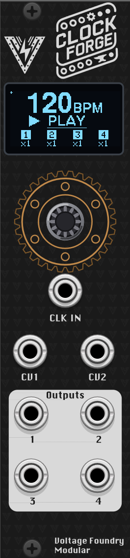
Hover the panel to zoom
Clock Forge
Forge SeriesAdvanced clock generator and modulator with four flexible outputs.
ClockForge 2: Crafting Time, One Pulse at a Time
Overview
ClockForge provides clock signals and waveforms for synchronizing and modulating other modules in your Eurorack system. It features a global BPM control, multiple clock outputs, adjustable clock multiplication and division per output, tap tempo functionality, sync to external clock sources, Euclidean rhythm generation, CV Input modulation matrix and custom swing patterns per output.
Part of the Forge series of modules which share a single hardware platform. The new ClockForge 2 is an updated version with a more powerful microcontroller and 4 outputs that can generate clocks, waveforms and envelopes.
Most parts of this manual applies to both Hardware and VCV Rack plugin with exceptions to hardware specific features like calibration, powering and firmware update. The VCV Rack plugin is a full software emulation of the hardware module and can be used to test the module without having the physical hardware.
The hardware schematics and design files are completely open-source and available in the GitHub repository.
Check the module on ModularGrid.
Features
- Global BPM Control: Set the global BPM for all outputs.
- Multiple Clock Outputs: Four clock outputs with individual settings.
- Adjustable Clock Multiplication and Division: Configure each output to multiply or divide the global BPM.
- Output Waveform Generation: Outputs can generate different waveforms for modulation.
- Pulse Probability: Set the probability of a pulse occurring.
- Euclidean Rhythm Generation: Generate complex rhythms using Euclidean algorithm.
- Custom Swing Patterns: Apply swing to each output individually.
- Sync to External Clock Sources: Automatically adjust BPM based on an external clock signal with adjustable clock divider.
- Phase Shift: Adjust the phase of the output in relation to the master clock.
- Waveform Duty Cycle and Level/Offset: Adjust the pulse width and level/offset of the clock signal.
- External modulation: Many parameters can be modulated by the CV inputs by assigning CV targets.
- Tap Tempo Functionality: Manually set the BPM by tapping a button.
- Quantization: Quantize the output wave or CV input to some scale and root note.
- Envelopes: Outputs can generate different types of envelopes (AD, AR, ADSR) triggered by CV inputs.
- Cross Operations: Modulate an output with another output or CV input using arithmetic, logic and sample/hold operations.
- Loops: Rewind an output’s pattern every few beats to build repeating, structured random/Euclidean phrases, with nap/wake muting.
- Save/Load Configuration: Save and load up to 10 configurations.
The module has a user-friendly interface with an encoder for navigation and parameter adjustment, and a clear display showing the current settings and status of each output. The main screen shows the BPM and the status of each output, while navigating into each output’s settings allows for detailed configuration of that specific output. There are no submenus as all parameters are accessible by scrolling horizontally on the same menu screen.
The right side of the screen shows a navigation line to indicate the current position of the cursor in the menu. The navigation is not shown in the main (BPM) screen.
Whenever a parameter is changed, a small circle will be shown in the top-left corner of the screen. This indicates that the current settings were modified and not saved. The module always loads the preset saved in slot 0 on boot.
The current hardware design supports input signals from 0 to 5V, and the outputs are also 0-5V. The VCV Rack plugin module can be set to accept CV signals in the range of 0 to 5V like the hardware, -5 to +5V or 0 to 10V for more flexibility. The hardware might support other input/output ranges in the future but for now, voltages higher than 5V will be clipped and voltages lower than 0V will be ignored.
User Manual
- ClockForge 2: Crafting Time, One Pulse at a Time
- Overview
- Features
- User Manual
- Operation
- Interface
- Setting the BPM
- Global Play/Stop
- Output clock division/multiplication
- Output Waveform
- Output Level and Offset
- Output Enable/Disable and Invert
- Pulse Probability
- Euclidean Rhythm Configuration
- Swing Configuration
- Output Phase Shift
- Duty Cycle (pulse width)
- Envelopes
- CV Input Modulation
- Cross Operations
- Loops
- Quantization
- Misc Settings
- Save/Load Configuration
- External Clock Sync
- VCV Rack Plugin
- Hardware Calibration
- Firmware Update
- Troubleshooting
- Powering
- Specifications
- Contact
- Acknowledgements
- License
Global Parameters
- BPM: Beats per minute, adjustable from 10 to 300.
- Master Stop: Stop or resume all outputs.
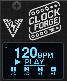
The small squares on the main screen show the status of each output. If the square is filled, the output is active. If the square is empty, the output is stopped.
Output Parameters
Each of the four outputs can be individually configured with the following parameters:
- Divider/Multiplier: Set the clock multiplication or division ratio.
- Output State: Enable or disable the specific output.
- Invert: Invert the output polarity (5V - value).
- Pulse Probability: Probability of a pulse occurring.
- Euclidean Enabled: Enable or disable Euclidean rhythm generation.
- Euclidean Steps: Number of steps in the Euclidean pattern.
- Euclidean Triggers: Number of triggers in the Euclidean pattern.
- Euclidean Rotation: Rotate the Euclidean pattern.
- Euclidean Pad: Add empty steps to the end of the Euclidean pattern.
- Swing Amount: Adjust the swing amount for the output.
- Swing Every: Set the pulse interval for applying swing.
- Phase Shift: Adjust the phase of the output in relation to the master clock.
- Duty Cycle: Adjust the pulse width of the clock signal.
- Level: Set the output voltage level.
- Offset: Set the output voltage offset.
- Waveform: Select the waveform for outputs.
- Quantization: Quantize the output to a specific scale and root note.
- Cross Operation: Combine this output’s value with another output or CV input using a selected operation.
- Loop: Rewind this output’s pattern every N beats, with optional nap/wake muting.
Operation
Interface
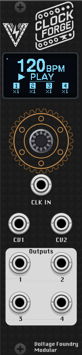
On it’s main page, the module shows the current BPM and the status of each output. The small squares on the main screen show the status of each output. If the square is filled, the output is active. If the square is empty, the output is stopped.
- CLK In: Optional CV Clock input (0-5V)
- IN1, IN2: CV input to control internal parameters via matrix (0-5V)
- OUT 1 / 2 / 3 / 4: Outputs which are waveform capable (0-5V)
Setting the BPM
- Use the encoder to navigate to the BPM setting.
- Push the encoder to enter edit mode.
- Rotate the encoder to adjust the BPM value.
- Press the encoder to exit edit mode.
Global Play/Stop
With the PLAY or STOP word underlined, press the encoder button to stop or resume all outputs. The individual outputs can still be stopped or resumed individually and will remain in the last state set.
Output clock division/multiplication
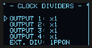
Outputs can be configured to multiply or divide the master clock. The default value is 1x which means the output will be in sync with the master clock. The outputs can be multiplied up to 64x or divided down to /128 with some triplets and dotted notes in between in the “1.5” and “3” division and multiplier values.
- Navigate to the selected output.
- Click the encoder to enter edit mode.
- Use the encoder to select the desired divider value.
- Click the encoder to exit edit mode.
Output Waveform
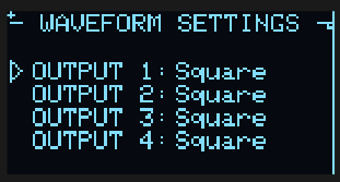
Outputs can be configured to multiple waveforms and envelopes.
They support the following:
- Square: A square wave with adjustable duty cycle, level and offset.
- Triangle: A triangle wave with adjustable duty cycle, level and offset.
- Sawtooth: A sawtooth wave with adjustable duty cycle, level and offset.
- Sine: A sine wave with adjustable duty cycle, level and offset.
- Parabolic: A parabolic wave with adjustable duty cycle, level and offset.
- Logarithm Envelope: A logarithm envelope curve (starts at 0% rising to 100%) with adjustable level and offset. Triggered by clock pulses.
- Exponential Envelope: An exponential envelope curve (starts at 0% rising to 100%) with adjustable level and offset. Triggered by clock pulses.
- Inverted Logarithm Envelope: An inverted logarithm envelope curve (starts at 100% decaying to 0) with adjustable level and offset. Triggered by clock pulses.
- Inverted Exponential Envelope: An inverted exponential envelope curve (starts at 100% decaying to 0) with adjustable level and offset. Triggered by clock pulses.
- Hatchet x2: Generates 2 square pulses in one up clock cycle. The pulse width can be adjusted by the duty cycle parameter. Level and offset can also be adjusted.
- Hatchet x4: Generates 4 square pulses in one up clock cycle. The pulse width can be adjusted by the duty cycle parameter. Level and offset can also be adjusted.
- Noise: A random signal with adjustable level and offset. Continuous.
- Smooth Noise: A smooth random signal with adjustable level and offset. Continuous.
- Sample & Hold: A sample and hold signal based on noise with adjustable level and offset. Triggered by clock pulses.
- AD Envelope: An Attack-Decay envelope (no sustain while gate is held) with adjustable level and offset. Triggered by a CV input.
- AR Envelope: An Attack-Release envelope (sustain is held at max level while gate is on) with adjustable level and offset. Triggered by a CV input.
- ADSR Envelope: An Attack-Decay-Sustain-Release envelope with adjustable level and offset. Triggered by a CV input.
- Play: The output will be true (high) when the master clock is running and false (low) when the master clock is stopped. This is useful for triggering other modules based on the master clock.
- Reset: The output will trigger (high) when the master clock starts running. This is useful for resetting other modules based on the master clock.
- CV 1 / CV 2: The output mirrors CV input 1 or 2 respectively (a buffered copy of the input voltage). Enable Quantize on the output to snap that CV to the selected scale and root note — handy for pitch-quantizing an external sequencer or random source. No CV target assignment is needed.
- Navigate to the selected output item. Click the encoder to enter edit mode.
- Use the encoder to select the desired waveform. The waveform will be updated in real-time.
- Click the encoder to exit edit mode.
Output Level and Offset
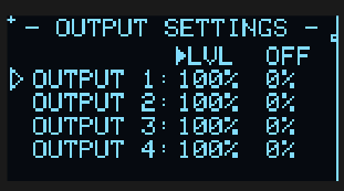
Allows setting the output level and offset which ranges from 0 to 100% corresponding to 0 to 5V.
- Navigate to the selected output. Click the encoder to enter edit mode.
- Use the encoder to select the desired output level from 0 to 100% which corresponds to 0 to 5V.
- Click the encoder to exit edit mode.
Output Enable/Disable and Invert
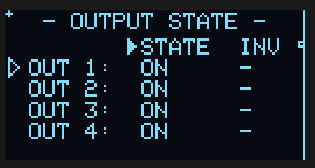
The Output State page has two columns per output: STATE and INV.
Outputs can be stopped individually (STATE). When stopped, the output will not generate any pulses. When master stop is activated, all outputs will be stopped and when master play is resumed, any stopped output will be kept stopped.
The INV column inverts the output polarity (the final voltage becomes 5V − value), so a rising ramp becomes falling, and a high gate becomes low. This is applied at the very last stage, after cross-operations and quantization. (Note: inverting a quantized pitch mirrors it around mid-scale rather than transposing it, so invert is mainly useful for gates, triggers and modulation shapes.)
- Navigate to the output state menu page.
- Use the encoder to move between the STATE and INV columns for each output (the arrow indicates the active column).
- Click the encoder to toggle the selected output’s state (ON/OFF) or invert (Inv/-).
Pulse Probability
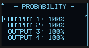
This is the percentage of probability that a pulse will be generated on the output. This is useful for creating random patterns or adding some variation to the output.
- Navigate to the probability menu page.
- Click the encoder to enter edit mode on the selected output.
- Use the encoder to select the desired pulse probability in percentage.
- Click the encoder to exit edit mode.
Euclidean Rhythm Configuration
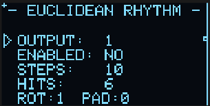
Euclidean rhythms are generated by an algorithm that takes a number of steps, a number of triggers (HITS — the active steps) and a rotation (ROT) of the pattern, then spaces the hits as equidistant from each other as possible. See https://en.wikipedia.org/wiki/Euclidean_rhythm for more info.
Additional empty steps can be added to the end of the pattern using the pad (PAD) parameter. This is useful for creating more complex rhythms.
- Navigate to the euclidean rhythm menu page.
- Select the output item and click the encoder to select the output to be edited. Click the encoder again to exit the output selection.
- First setting enables or disables the Euclidean rhythm generation by clicking the encoder.
- Select the Steps, Triggers and Rotation parameters, click the encoder to edit the values.
- The pattern will be updated in real-time and displayed on the right of the screen. Euclidean rhythm allows up to 64 steps but only the first 47 are displayed. Rhythm steps are shown in columns, top to bottom, left to right.
The euclidean rhythm pulse is affected by the pulse probability setting.
Swing Configuration
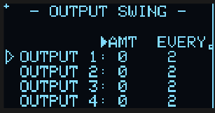
The outputs can have a swing pattern applied to them. The swing amount is in 1/96th of a note based on current BPM and the swing every is the interval between applying the swing. The swing amount can be set from 2/96th to 12/96th delay and the swing every from 1 to 16 pulses.
- Navigate to the selected output. The first parameter to be edited is the swing amount.
- Click the encoder to enter edit mode.
- Use the encoder to select the desired swing amount.
- Click the encoder to exit edit mode.
- Navigate to the selected output, the second parameter to be edited is the swing every.
- Click the encoder to enter edit mode.
- Use the encoder to select the desired swing every value.
- Click the encoder to exit edit mode.
Output Phase Shift
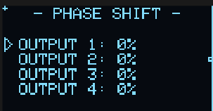
Outputs can have their phase adjusted in percentage in relation to the master pulse. This allows for phase shifting the output in relation to the master clock. The default value is 0% which means the output is in phase with the master clock. An adjustment of 50% will shift the output by half a pulse width, which means this output will hit on the upbeats of the master clock (or of an output with a 0% phase shift).
Just be careful with phase wraps as shifting an output phase by more than 50% with a duty-cycle bigger than 50% can lead to unexpected triggers.
Duty Cycle (pulse width)
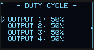
Duty cycle or width is the percentage of the pulse that remains high or low. The default value is 50% which means the pulse high cycle has the same length as the low cycle. The duty cycle can be set from 1 to 99% where 1% will generate a very short pulse and 99% a very long high pulse.
The non-square waveforms can also have their shape modified by the duty cycle parameter. For example, a 50% duty cycle (default) in the triangle wave output will generate a perfect triangle wave, setting the duty cycle to 1% will generate a sawtooth wave and setting it to 99% will generate an inverted sawtooth wave. The duty cycle also affects the envelopes by shortening or lengthening the decay time during the pulse.
- Select the duty cycle parameter for the desired output. Click the encoder to enter edit mode.
- Use the encoder to select the desired duty cycle value from 1 to 99%.
- Click the encoder to exit edit mode.
Envelopes
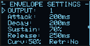
The module supports envelope generators based on input CV triggers. Refer to the Output Waveform section for more information on setting the envelope types.
The AD, AR and ADSR envelopes can only be generated by using triggers/gates on the CV inputs. They can have configurable curves between logarithmic, linear and exponential and also allow retriggering while the envelope is still active. The other waveforms (square, sine, Exp Env, Log Env and its inverted modes, etc) cannot be triggered by CV inputs.
To set an envelope generation, follow these steps:
- Go to the waveform selection and choose between “AD Env”, “AR Env” or “ADSR Env”.
- Go to CV Input target configuration, select which CV input will receive the gate/trigger and assign it to the Output X Env parameter.
Tip: You can have up to 2 envelopes running at the same time, as there are only 2 CV inputs that can be assigned as triggers. Each output can have its own parameters like envelope type, levels, offsets, curves and retriggering settings.
Adjust the envelope parameters like Attack, Decay and Release times, Sustain level, curve percentage and retriggering to your needs.
CV Input Modulation
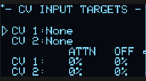
Many parameters can be modulated by the CV inputs. The CV inputs are 0-5V and can be used on the modulation matrix to control the parameters below:
- Start/Stop: Start or stop all outputs with a gate/CV signal (high = play, low = stop).
- Reset: Reset the clock on a rising edge.
- BPM: Modulate the global BPM with a CV signal.
- Output X Div: Modulate the clock division/multiplication for output X.
- Output X Prob: Modulate the probability of a pulse occurring on output X.
- Swing X Amount: Modulate the swing amount for output X.
- Swing X Every: Modulate the pulse interval for applying swing on output X.
- Output X Level: Modulate the output voltage level for output X.
- Output X Offset: Modulate the output voltage offset for output X.
- Output X Waveform: Select the waveform for output X based on the input CV Value.
- Output X Duty Cycle: Modulate the duty cycle of the output X.
- Output X Envelope: Trigger the envelope generation for the output X by sending a gate/trigger signal to the assigned CV input.
To route a CV input straight to an output (e.g. to quantize an external CV), no target assignment is needed — set that output’s waveform to “CV 1” or “CV 2” instead (see Quantization).
Each input can be assigned to one of the parameters above. The CV input can be attenuated or offset by using configuration parameters.
- Navigate to the selected CV Input parameter.
- Click the encoder to enter edit mode.
- Use the encoder to select the desired parameter to be modulated.
- Click the encoder to exit edit mode.
- Optionally, navigate to the attenuation and offset parameters for each CV input and set the desired values in a similar way.
The CV target is only applied to the selected parameter when the user exits edit mode. This way, a CV connected to an input does not change the scrolled parameters while the user is selecting the target.
Cross Operations
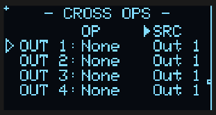
Cross operations allow the value of an output to be influenced by another signal (a source) through a selected operation. This can be as simple as mixing two outputs together, a logic gate, or something more involved like sample-and-hold or reseeding randomness. It greatly extends the basic logic operations found on similar modules.
The Cross Ops menu page has one row per output with two columns:
- OP: the operation to apply (set to anything other than “None” to activate).
- SRC: the source signal — another output (
Out 1–Out 4) or a CV input (IN 1,IN 2).
When a source is another output, its value is taken before that output’s own cross operation is applied, so two outputs can cross-modulate each other without feedback and the result is independent of output order. Cross operations are applied before quantization, so you can, for example, mix two pitches and then quantize the result.
- Navigate to the Cross Ops page and the desired output row.
- Click the encoder to edit the OP column and select an operation.
- Move to the SRC column, click to edit, and select the source output or CV input.
- Click the encoder to exit edit mode.
The available operations are:
- None: Cross operation disabled (output is unaffected).
- MIX: Average of the output and source values.
- MULT: Multiplies the two values (ring-mod style).
- ADD: Adds the two values, clipping any overflow.
- SUB: Subtracts the source from the output, clipping at zero.
- MIN: The lower of the two values.
- MAX: The higher of the two values.
- HOLD: While the source is high, the output value is frozen at its last value.
- S&H: A rising edge on the source samples the current output value and holds it until the next rising edge.
- MASK: When the source is zero, the output is forced to zero; otherwise it passes through.
- NOT: When the source is high, the output is forced to zero (inverse of MASK).
- OR / XOR / AND: Boolean logic of the two values, outputting either zero or full scale (like CMOS logic gates).
- BitOR / BitXOR / BitAND: Bitwise logic across all bits of the two values, for more complex stepped results.
- SEED: A rising edge on the source rewinds this output’s random generator, replaying the same random sequence from the start (useful for “Krell”-style patches). The value passes through unchanged.
Logic operations treat a value above half scale as “high”. The HOLD, MASK, NOT, S&H and SEED operations treat any value meaningfully above zero as “high/triggered”.
Loops
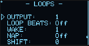
Loops turn free-running or random patterns into repeating, musically structured phrases by periodically rewinding an output. A loop length is specified in beats (quarter notes, not steps), and at each loop boundary the output’s pattern generators — random values, probability decisions and the Euclidean step position — are rewound to their start, so the pattern repeats identically.
This is especially useful for random waveforms (Noise, Smooth Noise, S&H) and probability or Euclidean patterns: with a loop set, an otherwise endless random sequence becomes a locked, repeating groove aligned to the bar.
When a loop is active, the Nap/Wake parameters add a higher-level on/off arrangement counted in whole loops:
- Loop Beats: Loop length in beats.
Offdisables loops; otherwise 1–64 beats. - Wake: Number of complete loops to play (output active) before napping.
- Nap: Number of complete loops to mute the output.
Off(0) means the output never naps and just repeats. - Shift: Offsets the start of the nap/wake cycle by a number of complete loops, so different outputs can stagger their drop-outs against each other.
For example, with Loop Beats = 4, Wake = 2 and Nap = 1, the output plays the same 8-beat phrase (two 4-beat loops), then goes silent for 4 beats, then repeats. While napping the output is muted (0 V) but its timing keeps running, so it resumes in phase.
- Navigate to the Loops menu page.
- Select the OUTPUT item and click the encoder to choose the output to edit. Click again to exit the output selection.
- Set LOOP BEATS to the desired loop length (or
Offto disable). - Optionally set WAKE, NAP and SHIFT to build the mute pattern.
- Click the encoder to exit edit mode.
Quantization
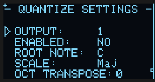
The module supports quantization of the output to a specific scale and root note. The quantization can be applied to the output waveform or to the CV input.
The Quantize Settings menu allows you to enable/disable quantization for the selected output, choose the root note, scale to be used and octave transpose with 3 octave levels higher or lower.
To use quantization on the generated output, first select the output waveform type (sine, S&H, etc) and then enable the quantization on Quantize menu. Select the root note and scale to be used. The quantization will be applied to the output waveform.
It’s also possible to quantize an input CV signal to a specific scale and root note. This is useful for using CV values generated by external modules (e.g. a sequencer or random source) to drive pitch. To do this, select the “CV 1” or “CV 2” waveform type for the output — this mirrors the corresponding CV input jack to that output. Then enable quantization in the Quantize menu and pick the root note and scale.
Eg. to quantize CV input 1 on output 3: set output 3’s waveform to “CV 1”, then enable Quantize on output 3 and choose the scale/root note. The CV input is copied to the output and snapped to the selected scale — no CV Input Target assignment is needed.
With quantization disabled, the “CV 1”/“CV 2” waveform simply passes the CV input through to the output (a buffered copy), which can be used as a CV mult/buffer.
Misc Settings
Tap Tempo
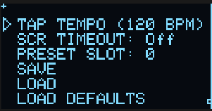
In addition to setting the BPM manually, the module can be set to the desired BPM by clicking the encoder. The module will calculate the BPM based on the interval between taps.
- Select the tap tempo parameter.
- Press the encoder button at least 3 times to set the BPM based on the interval between taps. If more than 3 taps are entered, the average time between the last 3 is used. BPM is updated in real-time.
Main screen timeout
The module can be set to return to the main screen (the one showing the BPM and the output boxes) after a certain amount of seconds of inactivity when not editing a parameter. When a parameter is being changed (selected), the timeout doesn’t apply. This can be configured in the “Screen Timeout” menu where the options are Off, 2s, 5s, 10s and 20s.
Save/Load Configuration
The module has 10 memory slots (0–9) to save and load configuration. The parameters saved into slot 0 are automatically loaded on boot.
- Navigate to the PRESET SLOT parameter.
- Click the encoder to enter the desired slot selection.
- Click to exit the slot selection.
- Select SAVE and click the encoder to save the current slot configuration.
- Select LOAD and click the encoder to load the selected slot configuration.
The “LOAD DEFAULTS” option will load the default configuration to current parameters but will not save it. To save the default configuration, navigate to the save configuration parameter and save it to the selected preset slot.
External Clock Sync
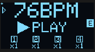
- Connect an external clock signal to the CLK IN input.
- The module will automatically adjust the BPM to match the external clock. A small “E” will be displayed on the screen next to BPM when the external clock is detected.
- When the external clock is disconnected, the module will revert to the last used internal BPM.
If the external clock is faster than needed (for example running at higher PPQN), it’s possible to apply an external clock divider (from no division to 48PPQN) to the input signal in the Clock Divider section.
The module works with external clocks from 30 to 300 BPM. Due to timer resolution, using very slow external clocks with high multipliers may lead to jitter on the outputs.
VCV Rack Plugin
The VCV Rack plugin is a full software emulation of the hardware module and can be used to test the module without having the physical hardware. The plugin saves and loads the configuration in the same way as the hardware module internally without the use of VCV Rack presets.
Some features of the VCV Rack module are exclusive to the plugin and not available on the hardware module. These include:
- Setting the input CV range to 0-5V or 0-10V or -5V to +5V. The hardware module only supports 0-5V.
- Setting the Encoder sensitivity.
Hardware Calibration
The module ships with sensible default values, but for best precision — especially when using quantization or 1V/oct pitch CV — you should run the hardware calibration wizard once after building or assembling the module.
Calibration covers two things:
Output trim: the output op-amp gain is set with on-board trimmers so every output jack delivers exactly 5.00 V at full scale. This is purely a hardware adjustment — there is no software output scaling.
CV input calibration: each CV input is measured at two known reference voltages (1 V and 3 V) to build a per-channel linear correction (mv = scale × reading + offset) that compensates for resistor tolerances and ADC offset. This is done with external references and is independent of the module’s own outputs, so any output-trim error does not propagate into the input calibration.
Calibration data is stored in a dedicated area of non-volatile memory separate from presets, so it survives firmware updates and preset load/save operations.
What you need
- A multimeter capable of measuring DC voltage to at least two decimal places (for the output trim).
- A stable, known 1 V and 3 V source for the CV inputs — for example a precision voltage reference, a bench power supply, or a calibrated sequencer/quantizer output — and a patch cable to connect it.
Running calibration
The wizard has 5 steps: one output trim followed by four CV input captures (1 V and 3 V on each of the two inputs).
Power on the module from your Eurorack supply while holding the encoder button pressed. The display shows the calibration wizard; release the button at the welcome screen and click the encoder to start.
⚠️ Calibrate on Eurorack power, not the MCU’s USB port — USB cannot drive the outputs to full scale, so the trim would be wrong. Never connect Eurorack power and USB at the same time, as this could damage the module.
Step 1 — Output trim (
1/5 OUTPUT TRIM): All four outputs are driven to full scale. Using a multimeter set to DC voltage, probe each output jack in turn and adjust its corresponding trimmer potentiometer on the PCB until the reading is exactly 5.00 V. When all four outputs read 5.00 V, press the encoder to continue.Steps 2–5 — CV input capture (
2/5…5/5): The display asks for a specific reference voltage on a specific input, in turn:2/5 CV1 INPUT 1V— apply 1 V to CV input 13/5 CV1 INPUT 3V— apply 3 V to CV input 14/5 CV2 INPUT 1V— apply 1 V to CV input 25/5 CV2 INPUT 3V— apply 3 V to CV input 2
For each step, apply the requested voltage to the named input. The screen shows a live voltage reading so you can confirm the signal is stable; when it is steady, press the encoder to capture (256 ADC samples are averaged). Repeat for all four steps.
Review and save: The display shows the derived per-channel scale and offset for a sanity check. Press the encoder to save and reboot. The module restarts with calibration applied.
Tip: Calibration only needs to be run once. Re-run it if you replace any resistors or trimmers on the board, or if CV tracking feels off after assembly.
Firmware Update
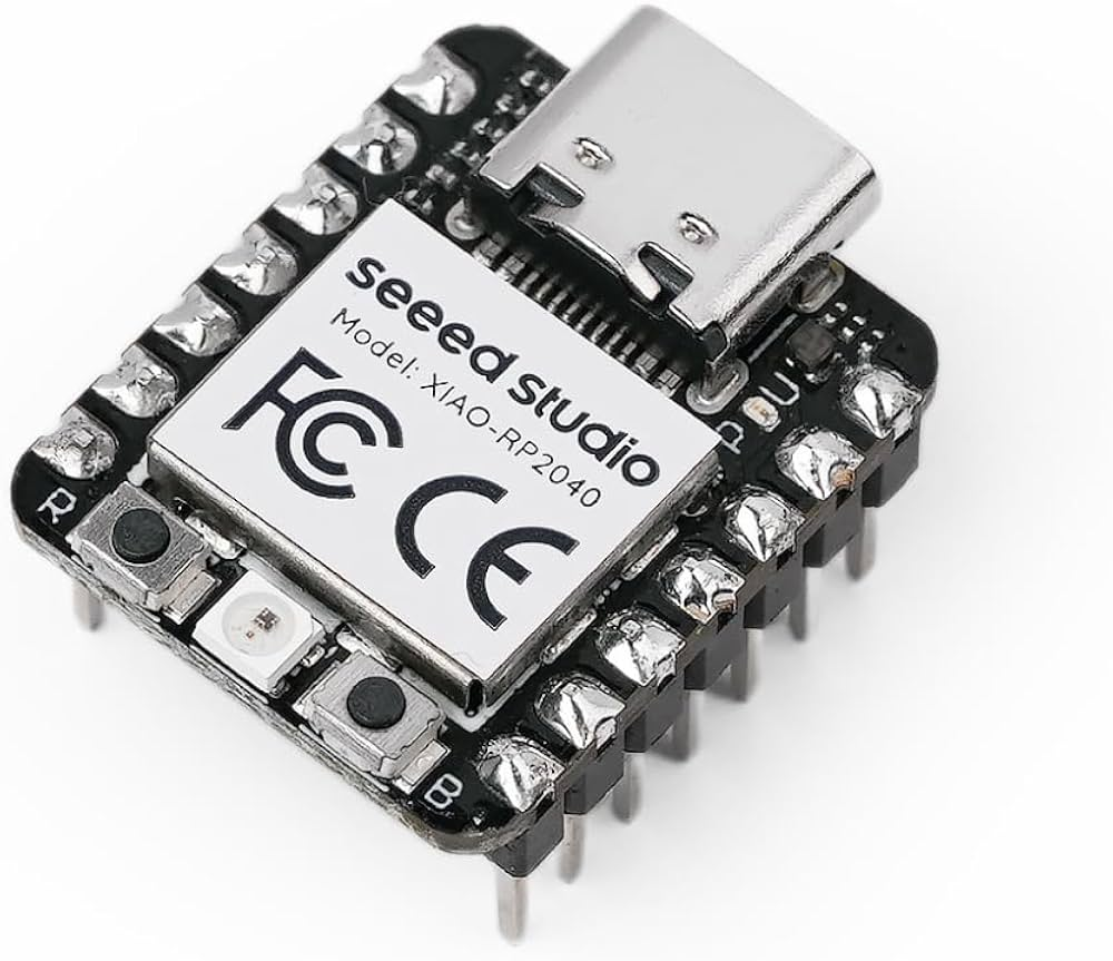
- Download the latest firmware from the Releases section of the GitHub repository. The firmware file is named
CURRENT.UF2. - Connect the module to your computer using a USB-C cable while holding the small BOOT (B) button. The CPU can be removed from the module as it’s socketed to the main board if desired. Firmware loading can be done with the CPU removed.
- A new drive will show on your computer named RPI-RP2. Copy and overwrite the
CURRENT.UF2file to the module USB drive. After copy is finished, the module will reboot and the new firmware will be loaded.
Troubleshooting
- No Power: Ensure the module is properly connected to the power supply and the power jumper is set correctly.
- No Output: Verify the board connections and output settings and ensure the module is not stopped.
- Inconsistent BPM: Ensure the external clock signal is stable and properly connected.
Powering
The module uses only 5V internally. This can be provided directly by a Eurorack supply with a 5V rail, or taken from the 12V line and converted to 5V on-board. The source is selected with an on-board jumper: closing the center pin to INT REG takes power from the Eurorack 12V supply, while closing the center pin to EURO takes power from the 5V rail (requires a 16-pin cable). It can also be powered from the USB-C jack on the microcontroller board.
Never connect both the Eurorack power and the USB-C power at the same time. The module might be damaged or even damage your computer if both are connected. The module is designed to be powered from either source, not both.
Specifications
- Power Supply: 12V or 5V jumper selectable
- Input CV Range: 0–5V
- Output CV Range: 0–5V
- Dimensions: 6HP
- Depth: 40mm
- Current Draw: 60mA @ +12V or +5V
Contact
For support and inquiries, please open an issue on the GitHub repository.
Acknowledgements
Parts of the code are inspired by Hagiwo code, Quinienl’s LittleBen and Pamela’s Workout. Thanks for the inspiration!
License
This project is licensed under the MIT License. See the LICENSE file for more information.
Thank you for choosing the ClockForge module. We hope it enhances your musical creativity and performance.